BACK TO AREA 0
draft – OSPF + NAT + BGP + AREA 0 over IPSEC
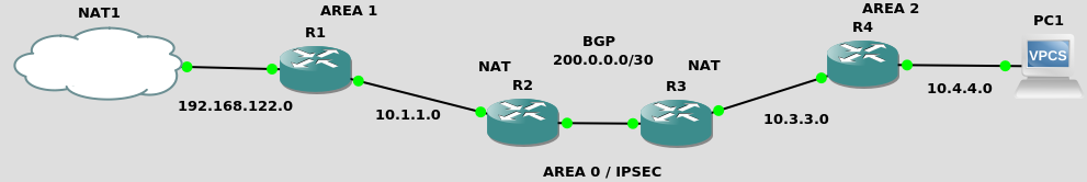
Two separated network locations
OSPF + NAT + BGP
We are NOT distributing the default route from R1 here, as we’ve done on the OSPF and BGP PoCs. We here rather assume the R2 and R3 routers are the default route for their respective network.
R2 (c7200)
interface FastEthernet0/0
    ip address 10.1.1.1 255.255.255.0
    ip nat inside
    ip ospf 1 area 1
    no shut

interface FastEthernet0/1
    ip address 200.0.0.1 255.255.255.252
    ip nat outside
    no shut

router ospf 1
    redistribute connected
    passive-interface FastEthernet0/1

router bgp 65000
    neighbor 200.0.0.2 remote-as 65002

ip nat inside source list 1 interface fa0/1 overload
ip nat inside source list 2 interface fa0/1 overload
access-list 1 permit 10.1.1.0 0.0.0.255
access-list 2 permit 192.168.122.0 0.0.0.255
R3 (c7200)
    interface FastEthernet0/0
            ip address 200.0.0.2 255.255.255.252
    ip nat outside
    no shut

    interface FastEthernet0/1
            ip address 10.3.3.254 255.255.255.0
    ip nat inside
            ip ospf 1 area 2
    no shut

    router ospf 1
            redistribute connected
            passive-interface FastEthernet0/0

    router bgp 65002
            neighbor 200.0.0.1 remote-as 65000

ip nat inside source list 1 interface fa0/0 overload
ip nat inside source list 2 interface fa0/0 overload
access-list 1 permit 10.3.3.0 0.0.0.255
access-list 2 permit 10.4.4.0 0.0.0.255
R1 (c3725) and its default route against the next hop
interface FastEthernet0/0
    ip address 192.168.122.196 255.255.255.0
    ip ospf 1 area 1
    no shut

interface FastEthernet0/1
    ip address 10.1.1.254 255.255.255.0
    ip ospf 1 area 1
    no shut

router ospf 1
    redistribute connected

ip route 0.0.0.0 0.0.0.0 10.1.1.1
R4 (c3725) and its default route against the next hop
interface FastEthernet0/0
    ip address 10.3.3.1 255.255.255.0
    ip ospf 1 area 2
    no shut

interface FastEthernet0/1
    ip address 10.4.4.254 255.255.255.0
    ip ospf 1 area 2
    no shut

router ospf 1
    redistribute connected

ip route 0.0.0.0 0.0.0.0 10.3.3.254
PC1
ip address 10.4.4.1/24 10.4.4.254
save
NAT1
    route add -net 10.1.1.0/24 gw 192.168.122.196
    route add -net 10.2.2.0/24 gw 192.168.122.196
    route add -net 10.3.3.0/24 gw 192.168.122.196
    route add -net 10.4.4.0/24 gw 192.168.122.196
route add -net 200.0.0.0/30 gw 192.168.122.196
AREA 0 over IPSEC
The big news here is that OSPF AREA 0 works over the secured pipe. Hence no need for the static routes against the other network location.
R2
crypto isakmp policy 1
 encr aes
 authentication pre-share
 group 2
crypto isakmp key beep-beep address 200.0.0.2
crypto ipsec transform-set some-transport-set esp-aes esp-sha-hmac
crypto ipsec profile some-ipsec-profile
 set transform-set some-transport-set

interface Tunnel0
 ip address 10.199.199.1 255.255.255.0
 tunnel source 200.0.0.1
 tunnel mode ipsec ipv4
 tunnel destination 200.0.0.2
 tunnel protection ipsec profile some-ipsec-profile
    ip ospf 1 area 0

!ip route 10.3.3.0 255.255.255.0 Tunnel0
!ip route 10.4.4.0 255.255.255.0 Tunnel0
R3
crypto isakmp policy 1
 encr aes
 authentication pre-share
 group 2
crypto isakmp key beep-beep address 200.0.0.1
crypto ipsec transform-set some-transport-set esp-aes esp-sha-hmac
crypto ipsec profile some-ipsec-profile
 set transform-set some-transport-set

interface Tunnel0
 ip address 10.199.199.2 255.255.255.0
 tunnel source 200.0.0.2
 tunnel mode ipsec ipv4
 tunnel destination 200.0.0.1
 tunnel protection ipsec profile some-ipsec-profile
    ip ospf 1 area 0

!ip route 10.1.1.0 255.255.255.0 Tunnel0
!ip route 192.168.122.0 255.255.255.0 Tunnel0
Network acceptance
ospf/nat/bgp
from R2
ping 200.0.0.2 source 10.1.1.1
from R1
show ip route
ping 200.0.0.2
from the host system (NAT1)
ping 200.0.0.2
area 0 over ipsec
from the host system (NAT1)
ping 10.3.3.254
ping 10.3.3.1
ping 10.4.4.254
ping 10.4.4.1
and you should see ESP datagrams on the wire in the center.
Resources
nat
https://cisco.goffinet.org/ccna/ospf/lab-ospf-multi-area/ –> 15. Activation de la connexion Internet IPv4
https://www.ciscomadesimple.be/2013/04/06/configuration-du-nat-sur-un-routeur-cisco/
https://www.practicalnetworking.net/stand-alone/cisco-nat-configurations-ios-router/
https://www.networkstraining.com/configuring-nat-on-cisco-routers/
default route
https://community.cisco.com/t5/switching/default-route-and-routing-protcols/td-p/1237502
Licensed as MIT